Verdict – whatever it is, a measurement device is it not. Better donate to some local villain, at least will the cash remain in the city.
I would say, it is a deceptive object created to play on the curiosity of naive westerners and to lure cash out of them. Very softly said, might be, it is a toy. I think it could a strong and shameful evidence you just sent some money to the Chinese communist regime to help them to establish their hegemonity over the western world.
Disqualifying fact no 1 – some Ebay descriptions claim: “Material: metal”. In reality, that thing is made from a cheap shi##y plastic. Ya’know, these DIY plastic enclosures for electronics projects in sub-$5 price region.
Disqualifying fact no 2 – it has a nice color display, has it? Well, technically the display is a two-color one. The upper part (the status line) shines RED and the lower two thirds green. Looks deceptively nice but the color isn’t actually used for the purpose. It’s like a 1960’s coloured filter on a B/W TV set.

Disqualifying fact no 3 – Take a screwdriver, do open the case and you’ll get a user experience not comparable with anything! Take a screwdriver and do open it. Prepare an expensive whiskey to create that holy moment of truth … just in seconds you get wiser for the whole 100 USD. You do not believe your eyes about what you will see inside – a 8mm sandwitch of PCB’s in an otherwise EMPTY plastic case. You were just sold a great piece of emptyness. My congratulations!

This is the photo of the PCB. If you are an engineer, try to find ANY characteristic element of an spectrum analyzer. Any waveguide? Any handmade 1013 MHz cavity resonator from Scotty? But nothing! I only see a fully digital PCB with the sole elements hinting to anything higher than HF are cheap front-side BNC connectors. Well … you may say … but it does work.

Works it yeah! – See, how it does.

Disqualifying fact no 4 – after switching it on (well-well, there is no switch – connecting it to the shaky +12V connector… and the screen starts scanning. What are you thinking HOW LONG will it take to scan the full screen? The answer was (I really measured it – 55 seconds).

I am claiming nothing, big professional spectrum analyzers (SA) too, have slow scan modes. But hey, is this the ONLY mode of work for this shi##y device? Ads claim you can tune your cavity duplexer with this. Yes you CAN. After making a half turn with your tuning screwdriver and then you wait half a minute to see the result on the screen. A productivity of work never seen before.
Some of the advertizing pics (d/loaded from the Ebay) illustrate the SA capabilities of the device – take your cheap Chinese walkie-talkie and push the PTT:
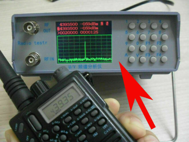
Technically the situation looks extremely truthworthy. But can you imagine, to shoot such a pic you have to push the PTT and then wait long 55 seconds for the full scan … and your transmitter is polluting the air all these 55 secs. Would you do it in a western capital? Our dear Chinese friends did it… to lure you into any further or as our Russian friends would say on the occasion – давай, засажу на ещё 5 см. Done!
Well, my friends, me too was decepting you, not only our Chinese friends. But I’ll help you out of this situation now. The issue is related to some unreasonable factory settings. Short press F1 two times or until the cursor get located right in the middle of the third line and do key in these digits: 0000200 (no ENTER needed). After that operation the screen refresh rate suddenly becomes 1.5 sec.
And this is the real signal straight from a transmitter. As you see, the noise around the signal is just deafening.

To tell the truth, the “silence” remains rather strong in the absence of the signal:

Technicians could want to see a more detailed view of the transmitted signal. Well … that’s possible, while the result probably cannot satisfy a trained eye. You don’t ask, me don’t tell.

Disqualifying fact no 5 – depending on the model you just bought, the input and output might be accidentally changed. Can you imagine a measuring device with such a deceptive marking – an input marked as an output and vice versa? Our friends Chinese have absolutely no problems with this situation. They just correct the situation in the their advertising materials. Like this:

Unf######believeable, eh? Do you want to see more? Only the ad materials call this device an SA. The device itself calls it “Radio Testr”:

A disclaimer: reverse engineering of the capabilities shows, the thingy aspires to be an extremely sh###y toy implementation of an “SA with the tracking generator”. More about it later.
Disqualifying fact no 6 – there are no sensitivity regulating controls at all. Just the AI living inside of the box and outputting dBm’s to the status lines.
Disqualifying fact no 7 – meaningless operating instructions.
And yeah, boys and girls, now will follow the most entertaining section of our today’s event. Because, nuff of the special effects – would you like to really operate the “instrument”?
Hello, but where are the operating instructions? Actually, right on the ebay. On your leisure time, you can try to translate these back to the mandarin language, like this phrase: “Package List:
– 1 xU/V UHF VHF dual band spectrum analyzer BNC with tracking source tuning Duplexer”
Huu! Wohin ist mein Duplexer? Should I initiate a dispute on the eBay?
Here are the operating instructions
(in a Mandarin dialect of standard English):
| The original description |
A possible translation |
| – The upper right corner of the spectrum shows the spectrum mode,the display tracking for the spectrum plus tracking mode |
We have provided some hieroglyphs in the right upper corner but considering your mandarin illiteracy, we will not dare to explain to you what these denote. |
| – The first line shows the center frequency center frequency power |
From the three red coloured status lines available, the first one is explicating the center frequency of the sweep span and the level of signal measured at that frequency, in dBm units. No explicit frequency markers are provided as in professional devices. |
| – The second line captures the strongest or weakest frequency, or the specified frequency and power (shows the capture of the strongest signal in capture mode, the acquisition of the weakest signal in capture plus capture mode, Adjust the diplexer steps “) frequency and power) |
We have the pleasure to announce it, that the device has some working modes. But we do not dare to inform you which modes these are. Sporadically the second line status will indicate the WEAKEST signal and sometimes the STRONGEST, but you have to deduce which one was the case. If you are lucky, the signal level will be indicated, but we avoid to say, is it a maximum or minimum – we denote it by an hieroglyph which you are illiterate to comprehend. |
| – The third line of the frequency range (center frequency plus or minus) frequency step |
On the third status line (also red), two editable values are shown: the center frequency (another one!) and the extent of deviation. We do not consider you worth to know whether the second number marks a deviation, span or step or the value of a measuring division. The experiments however show, the fastest updated narrowest bandwidth setting at the third line is: the first number: 0016000, the second number 0000050 (while using the “up”/”down” keys) or 0000800 and 0000005 in case of direct numeric input (but these values are unstable and can lead to the crash). |
| F1: cursor movement center frequency, frequency range,step cycle selection (long press to switch between spectrum and tracking mode) |
Get naxxuj, you start to bore me. Experiment yourself with the F1 button. We did. Seems like the “>” mark is the cursor. Pushing F1 shortly and repeatedly reveals three key numbers suspectible to the edit mode: The “center” frequency on the uppermost status line, the unknown value on the third status line (red) and the last one, a step value located at the second half of the third status line.
It seems to be impossible to influence the frequency shown on the second (middle) red line – that one is being direct driven by the AI living in the box. |
| F2: Backspace |
you, bastard, are not yet in a mode where that key could be effective. Be patient, until the dead corpse of the designer of this device passes by with the river flow. Otherwise, F2 erases the digit inputted last (except if it was the last digit of the input – because no ENTER key provided in pure Chinese style, the last digit will automagically conclude the input operation). |
| The cursor points to the center frequency: Numeric keys direct input or up and down keys to step to adjust the frequency |
When in edit mode at some of the input fields (by repeatedly short pressing F1), use “up” and “Down” keys to modify the respective frequency. |
| F3 F4 Adjust the frequency in 1M.The cursor points to the center frequency: Numeric keys direct input or up and down keys to step to adjust the frequency. The cursor points to the center frequency: Numeric keys direct input or up and down keys to step to adjust the frequency. |
Pressing the “up” and “down” keys will change the frequency 12.5 kHz, and the F3 and F4 keys respectively modify the relevant frequency by 1MHz. No decimal point indicated, you have to imagine it. |
| The cursor points to the frequency range: the value is centered on the center frequency plus or minus the range,for example: 0128000 as the center plus or minus 12.8 M |
a special message to military servants of PLA of China: we just repeated what we already said before. And yes, btw, the span value is indicaed in Khz not MHz units. |
| That is 25.6M range |
The frequency span value will be doubled compared to what has been shown. The same number of Khz down the center freq and then again up the center freq. Thus the real frequency span is twice so wide as you just entered. |
| Enter the number keys directly up and down keys to increase or decrease the range, |
it is your choice whether to change the span and center values in small chunks by “Up”, “Down”, F3 and F4 keys, or enter the frequency values directly (7 digits expected). No decimal points will be visible. |
| The cursor points to the step: the number keys directly input or the up and down keys to adjust the step change in 5K scan range will be slightly changed to fit the size of the grid |
if you have moved the cursor (by F1) to the step value, then the increment is 5 kHz (and not 12.5 Khz as indicated above). And, the F3 F4 keys are not working but we avoided to inform you about it. |
– – – – – – –
Disqualifying fact no 7 – if you push the “Down” button (actually “v”) while editing the “step” value, then the value within the field will be raised. And vice versa, the “^” button will decrease the value. This was probably made by intent – to turn all westerners mad. Up is down, black is white and bad is good.
The summary: after playing with the thingy for an hour or so, it’s still not possible to understand such important details as:
- what the “modes” mean and what does the long push of F1 actually change? Hieroglyphs on the screen – for sure! And then? At least regarding my particular device I have been unable to see the output from the tracking generator.
- what is the left number on the third status line meaning? Pushing “Up” and “Down” results in weird changes (multiples of 32000).
- what is the second number on the line three denoting? Span/step/range? Changing this number will change the display scan/refresh rate and will also influence the preceding number.
- The spectrum analyzer mode works for sure. But what is the toy measuring? Fluctuating electrons hitting a p-n transition? Might be, creature Zog is living inside the device expecting to tell me something? In case of a professional device, I would expect some protective grounding caps covering the input connectors … nothing such was amended with the device.
- I have not yet been successful in switching over to the tracking generator mode. I connected the input to the output and was expecting to see an horizontal line at the top of the screen. No success despite the repeated long presses of F1 – just the hieroglyphs changing. Is the tracking generator working at all or is it just generating random birdies? It seems like the quality control at the factory is extremely weak.

A curious question – Is there anything that works nice?
- Absolutely, e.g. it the box retaining your three precious input values after the reboot (mostly, except the crashes). That despite the fact you are unable to understand what two of these actually denote.
- And then a miracle – none of the push-buttons is yet glitching (as expected from Chinese production) but hey, it is only the first day of the use!
The insides
One can clearly identify the three chips on the PCB and deduce the underlying idea of the toy.
The one marked as STC 8f2k32s2 is the processor.

The chip marked as AT1846S (PDF) is “a highly integrated single-chip transceiver for Walkie-Talkie applications” generating the output frequencies.

Last but not least, the chip marked as SX1278 (PDF) is a “137 MHz to 525 MHz Long Range Low Power Transceiver” or just Lora tranceiver,

Both of the latter chips are able to transmit and to receive the signals … likely also to evaluate the signal strength (might it be – logarithmically?). Can this explain the mess of the designers have had with the In and Out connectors?
The nasty issue is, the toy isn’t doing what can be assumed it does. The tracking generator functionality is missing from my device.
Some another day I will measure the toy with a SDR and try to demonstrate a “cavity resonator” to it. Might be, in a company of good old friends, the thingy will improve the behavior ;)?
—
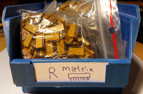
The verdict – never, I repeat EVER buy it. It’s a piece of excrement from Industry 4.0 backyard. Better just throw your cash away, seed it from the helicopters or smth like that. Do not support the communist regime. That box is not worth more than a couple of possibly reusable chips within it, minus what you would pay for a qualified SMD desoldering.
A note to my Estonian friends – no niukest paska nigu see, annab ikka tikutulega otsida.