(An ideological excursus)
Yes indeed, I have got an ungodly idea to build a CNC mill/router from scratch – not for the dire necessity but for fun and new knowledge. As with any design, there are numerous choices to be made.

It is generally agreed that a breakout board does contain neither stepper drivers nor the power source (PSU) for the steppers. A DIY board should be flexible to maximum extent, because a CNC beginner does not yet know what he actually wants.
The most expensive way is to buy a ready-made solution. However, that is not the most interesting path to take. Probably the easiest route to go is to shop at eBay or Aliexpress and to purchase a router table together with a CNC kit or, as an alternative, a cheap Chinese controller . However, curing those fine Chinese optimums/compromises could be a very tough topic .
It is obvious that he decisions between the software (commercial Mach or LinuxCNC) and hardware are inter-related. However, as one probably have understood, I have no particular goal beside mapping the (mine)field. The key success element is the breakout board. Why? Because that tiny item will connect the virtual world (PC) with the real world (router/mill).
Cabling considerations
Almost all available DIY designs still don’t use USB port for the interface. The issue seems to be the cost, because USB connectivity cards seem to reach USD200 these days. Yes we know – the LPT port is outdated and laptops do not have it. However, it is not a problem for me, because I have plenty of old hardware available. Old hardware can be obtained for nothing (well, 20-30€) these days. The beauty of the LPT interface is – it can be easily debugged while the USB interface certainly isn’t.
Some of the questions are not obvious at all. Why do most of the DIY designs use an DB-25 to DB25 straight cable (i.e. a serial cable)? As for me, I have plenty of high quality DB25 to Centronics 36-pin cables available (and, there are second hand shops around which sell these cables for €0.50).

Last but not least, I like to dismantle old printers (nuff details available only for 3..5€). It means, I have plenty of high-quality Centronics receptacles available in my scrap box. The pins distance for the Centronics-36 connector is 2.16mm and the row distance is 4.29mm [http://www.assmann-wsw.com/fileadmin/catalogue/03_Centronics_rev4-0.pdf] while the pin distance for DB-25 connectors is 2.76 mm and the row distance is 2.84mm [https://en.wikipedia.org/wiki/D-subminiature]. For home-grade PCBs, it means, the challenges in one-side PCB routing could differ, too.

To make my own design, I needed the “correspondence table” between the DB-25 and Centronics 36 interfaces. Because the Internet could only be trusted to an extent, I obtained and measured a couple of real cables. Some of them are “more equal” than others. Thus, one should exercise some care, because some cheaper cables have their own problems (extra pins connected, a ground common to many signal pins, pure coaxiality vs a “grounded bunch”, lower grade plastic etc).

Number of the Axes
To comply with standard software, one has to consider the limitations of the LPT interface. Generally, there are 8+4=12 outputs available and 5 inputs. To be crystally clear, hardware pins 1,14,16,17 normally used for outputting actually are bi-directional, however, the problem is that one usually needs more outputs and less inputs and not the 8 outputs 9 inputs combination achievable this way.

src: https://en.industryarena.com/forum/how-i-fixed-my-chinese-tb6560-controller-updated–110986-55.html
There are two favourite ways to enumerate the outputs. Having only 3 axes (X,Y,Z), it is possible to dedicate 3 pins for the channel (Step, Dir., Ena.). Should we need 4 axes, the compromises will start: each of four channels only having Step and Dir. pins and then there is a common enable pin. Of course, the software has to be aware of that kind of compromise made. Some rources claim, the ENABLE signal is a rudiment and they can manage without it.
As an example, we analysed three DIY designs and we are providing the pinout tables for each solution.
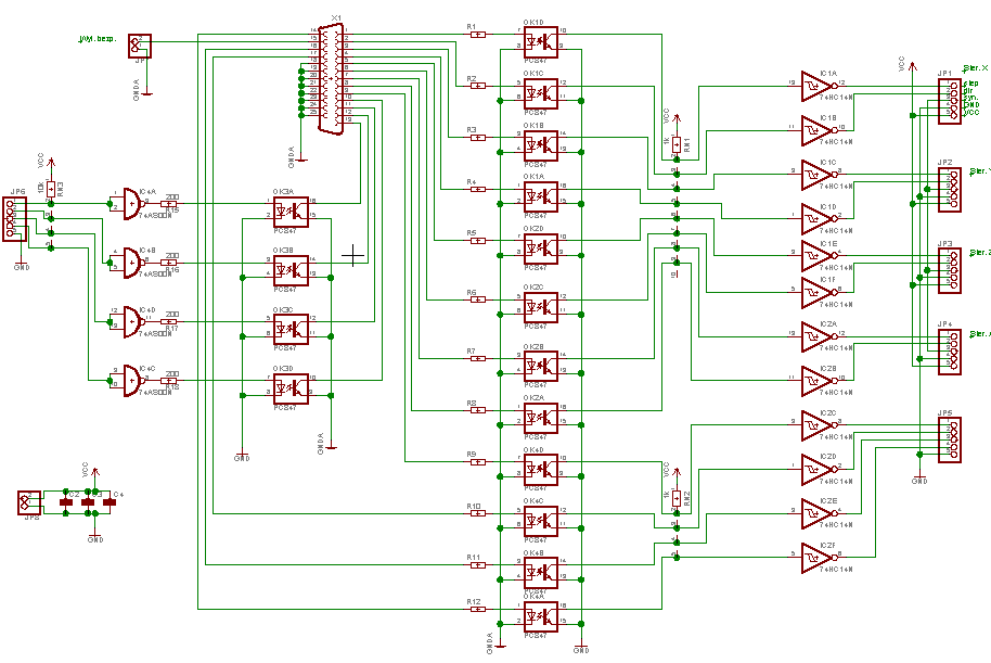
This is the schematics of the design (click to enlarge):

and this is the system analysis (a 4-axes system with a common ENABLE line):

Then, DIY artefact 2:
Here is the schematics of the design (click to enlarge):

and, the system analysis of that (of a a clean 3-axes design):

Last but not least, DIY artefact 3 (see the original PDF schematics):

and, the system analysis of it (the most universal design, lines/pins are not pre-designated):

As one might have noticed, two of the three sources are in Russian language. To make the landscape more thorough, let’s have a look at a summarizing picture from a Polish source analyzing various controllers:

Speed and thunder aspects
The LPT port per se is a relatively speedy device – ensuring speeds like 50 kbytes .. 150+ kbytes per second. The issue is, an LPT port is not safe from the electrical standpoint. Any quirk with the mains cabling could put LPT schematics under the electrical stress and burn it out/through. In most cases the LPT port is hardwired to the computer motherboard, that inevitably means the loss of the mobo in case of a lightning attack or mains quirk. Thus – do not risk, implement some galvanical separation! The separation is not so easy to implement as it seems, because, the chips used on the break-out board need some voltage to work and, additionally the VCC and GND lines for the PC vs the CNC side must be completely separated. If not so, the owner’s cat (named Murphy) will touch the cable while both devices are powered on… Many cheap designs seem to include that kind of an error.
And now about the main issue – the devices used for galvanic separation might be too slow. E.g. do look a discussion at LinuxCNC board, people claim, careless design will limit stepper frequency to 2-4 KHz. While other sources state, 15-20kHz might be necessary for fast enough movement of the router head (and yes, we are still speaking about the classical design not about these modern GRBL centaurs).

First, let’s agree the terminology. English language seems to miss a very important word – the optron. In former Eastern block, the word optron denoted any “optically coupled device for galvanic decoupling”, e.g. optocoupler. For historical reasons, I prefer the term optron over the optocoupler (particularly for the reason that in my mother tongue, the optocoupler gets translated too vaguely).
Said short, there are fast and slow optrons. The cheap and slow one is PC817 while the fast and more expensive ones are 6N137 and/or HPCS2630. One can find a good source on optron families here .
DIYers try to use fast optrons at least on STEP and DIR (and sometimes ENABLE) lines while the slow ones are permissible on the remaining channels. It seems so weird that DIYers are spending hours while trying to spare some dollars and are using cheaper optrons on auxiliary channels (ya’know – unification goals!). However, in various countries. people experience various ratios of free time to salary, thus let one do what one wants.
The simplest building block for an optron looks like this:

A crash course in optrons could be expressed by a summarizing figure:

Any buffering needed?
Indeed, some of the designs seem not to buffer at all. E.g. DIY artefact 4:

But some designers like to have 74HC14 chips after the optocouplers, not before these, see DIY artefact 5:

An interesting design direction is not to use Schmitt triggers to condition the signal but buffering chips – look at the DIY artefact 6 :

Nevertheless, the majority of DIY designers seem to use 7414 Schmitt triggers for the purpose, see DIY artefact 7:

However, there are more simple solutions around, e.g. using an ULN2008 driver to “empower” the critical lines, see DIY artefact 8:

